Copyright © VPA Systems sa | Designed by neoSG bvba


Step 1 : Create your sheet metal parts
Start from 2D profiles, 3D curves, 3D solids, or imported parts and assemblies. Create complex parts with lofted bends or automatically recognize them in imported geometry.
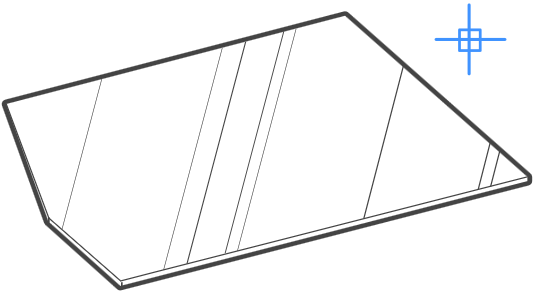
Create base flanges from 2D profiles
Create lofted bends from 3D curves
Make shells from 3D solids
Import sheet metal parts from other CAD systems
Step 2 : Rework your design
Rework your sheet metal part without limit
Add flanges by pulling edges
Move and rotate flanges
Split and connect flanges
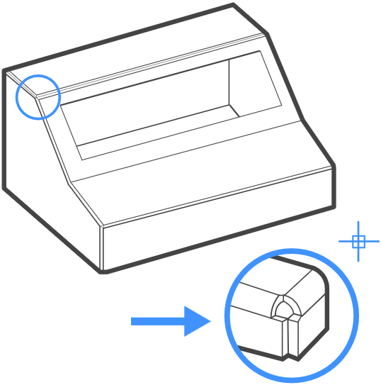
Add corner and bend reliefs
Convert hard edges to bends and junctions
Switch between bends and junctions
Choose type of corner reliefs (rectangular, circular or v-
Delete redundant flanges
Re-
Step 3 : Finish your sheet metal model
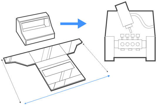
To prepare your design for manufacturing, sheet metal parts can be unfolded automatically and then exported to 2D .dxf or 3D .osm files for further processing with a variety of computer-
Unfold sheet metal bodies
Export flat patterns
Send 3D models to CAM systems
Quick Design Process
Creating new sheet metal parts or reworking existing ones? BricsCAD is your best choice. It is free of conceptual mistakes of history-


Bricscad is the powerful DWG-
BricsCAD for VidCAD
BRICSCAD


